An iron core is surrounded by a control coil. The diagram shows an inner section diagram of a relay. Molded frame – Relays are covered with plastic for protection. .Normally close – not connected when the relay is activated, and connected when it is inactive.ĥ. .Normally open – connected when the relay is activated, and disconnected when it is inactive. Set of electrical contacts – There are two contact points: Spring – When no currents flow through the coil on the electromagnet, the spring pulls the armature away so the circuit cannot be completed.Ĥ. And the armature can be moved with direct current (DC) as well as alternating current (AC).ģ. When current flows through them, the coil is it energized thus producing a magnetic field which is used to make or break the normally open (N/O) or normally close (N/C) points. Armature – The movable magnetic strip is known as armature. When electricity is passed through, it becomes magnetic. Electromagnet – It consists of an iron core wounded by coil of wires. The working of a relay can be better understood by explaining the following diagram given below.ġ.
#Arduino relay modules series#
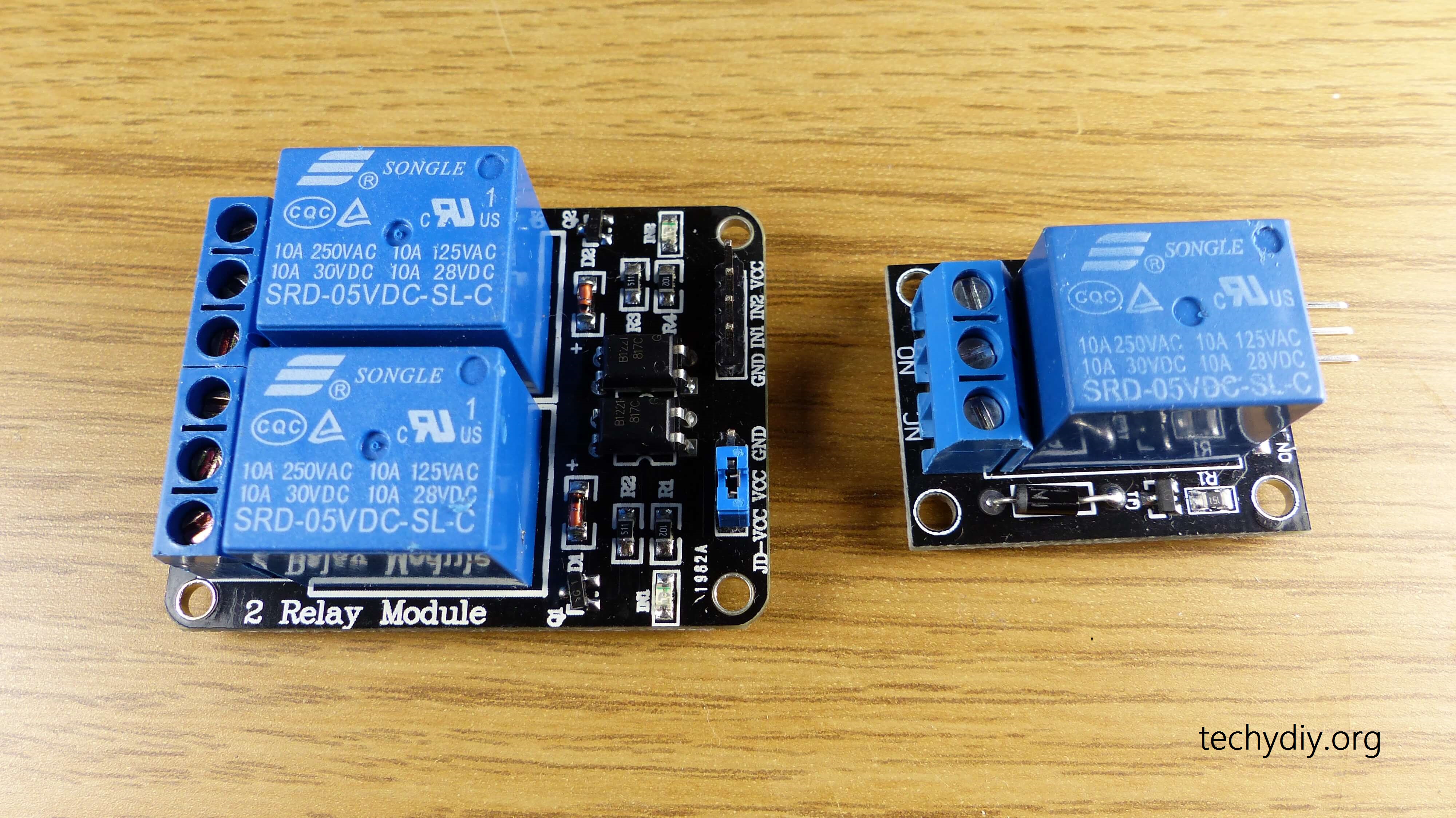
The 1 channel relay module could be considered like a series switches: 1 normally Open (NO), 1 normally closed (NC) and 1 common Pins (COM). SIG – Controls this relay, active Low! Relay will turn on when this input goes below about 2.0V.It has a 1×3 (2.54mm pitch) pin header for connecting power (5V and 0V), and for controlling the relay. With a normally-open (NO) contact and a normally-closed (NC) contacts.Being able to control high load current, which can reach 240V, 10A.1-channel high voltage system output, meeting the needs of single channel control.In power system and high voltage system, the lower current can control the higher one. The features of 1-Channel Relay module are as follow:.NB: input into a relay can be divided into two categories: electrical quantities (including current, voltage, frequency, power etc.) and non- electrical quantities(including temperature, pressure, speed, etc.) Features When the rated value of input (voltage, current and temperature etc.) is above the critical value, the controlled output circuit of relay will be energized or de-energized. There is an intermediary part between input part and output part that is used to coupling and isolate input current, as well as actuate the output. It also contains an actuator module (output) which can energize or de-energize the connection of controlled circuit. Generally speaking, a relay contains an induction part which can reflect input variable like current, voltage, power, resistance, frequency, temperature, pressure, speed and light etc. It is widely adopted in devices of power protection, automation technology, sport, remote control, reconnaissance and communication, as well as in devices of electromechanics and power electronics. The advantages of a relay lie in its lower inertia of the moving, stability, long-term reliability and small volume. To put it simply, it is an automatic switch to controlling a high-current circuit with a low-current signal. It is frequently used in automatic control circuit. It has a control system and (also called input circuit or input contactor) and controlled system (also called output circuit or output cont actor). Osoyoo Basic Board (Fully compatible with Arduino UNO rev.3) x 1Ī relay is an electrically operated device.
#Arduino relay modules how to#
In this lesson, we will show you how the 1-Channel Relay Module works and how to use it with the Osoyoo Uno board to control high voltage devices. Relays are used where it is necessary to control a circuit by a separate low-power signal, or where several circuits must be controlled by one signal. Many relays use an electromagnet to mechanically operate a switch, but other operating principles are also used, such as solid-state relays. If this sound is not compatible with your application, you will have to turn to the use of transistor(DC) or triac(AC).Note: ALL OSOYOO Products for Arduino are Third Party Board which is fully compatitable with Arduino IntroductionĪ relay is an electrically operated switch.

When the relay closes, the LED lights up and it emits a mechanical sound. On some relay modules there is an LED to help you observe the status of the relay. Parameters const int digPin = 2 void setup ( ) Result For this we use the digitalWrite() function.

#Arduino relay modules code#
The code to drive a relay is as simple as setting a pin high or low.

For example, the relay cuts off the circuit feeding the boiler in case of a problem to prevent it from heating continuously. Generally, the safest mode is chosen in case of a control failure.


 0 kommentar(er)
